Digital Systems
 4 min read
ADC and DAC
An ADC turns a voltage into a number and a DAC turns a number back into a voltage. Resolution in bits and the reference voltage decide the step size, so a 12-bit converter on 3.3 V resolves steps of about 0.8 mV.
From voltage to number
A microcontroller only understands bits, but the world gives it voltages from sensors. An analog-to-digital converter measures the input against a reference voltage Vref and returns an n-bit code. With n bits there are 2^n codes, so the code is the input divided by Vref, scaled to that range.
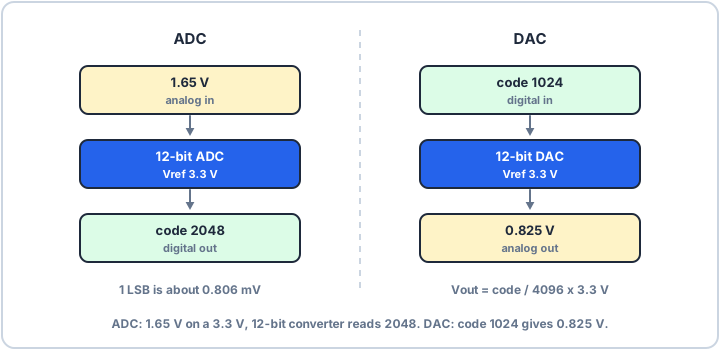
Take a 12-bit ADC with Vref = 3.3 V. There are 4096 steps, so one step (one LSB) is 3.3 V / 4096, about 0.806 mV. An input of 1.65 V, half of Vref, reads as code 2048. Any input inside one step gives the same code, so an ideal converter's quantisation error is at most ±½ LSB.
float volts = (adc_code * 3.3f) / 4096.0f; // code 2048 -> 1.65 VDividing by 4096 is the usual convention, but the top code is 4095, so full scale reads one step below Vref.
How it measures
Many microcontroller ADCs are successive-approximation (SAR) converters. They guess the top bit, compare it with the input, keep or drop it, then try the next bit, so an n-bit result takes n comparisons: a binary search for the voltage. Check your chip's reference manual for the exact conversion time, which depends on the sampling time you set.
The ADC also samples over time. To capture a signal faithfully, sample at more than twice its highest frequency (the Nyquist rate); slower sampling folds fast signals into false slow ones, called aliasing.
From number to voltage
A digital-to-analog converter works backwards: Vout = code / 2^n × Vref. With the same 12 bits and 3.3 V, code 1024 gives 3.3 V × 1024 / 4096 = 0.825 V. Inside, a common design is an R-2R ladder, a network of two resistor values where each bit switches in a binary-weighted share of the voltage. The output moves in steps, so a smooth waveform needs a low-pass filter after it.
Resolution and reference together set the accuracy, but noise, a noisy supply and the sensor's source impedance often matter more. A clean Vref is part of the design.