Digital Systems
 4 min read
Latches and flip-flops
Sequential circuits have memory: the output depends on past inputs as well. Feed a gate's output back into another gate and the pair holds a bit. A D flip-flop adds a clock, so it captures its input only at one instant, the clock edge.
A loop that remembers
Connect two NOR gates so each one's output feeds the other's input, and you get an SR latch. Its two inputs are Set and Reset. Pulse S to 1 and the output Q goes to 1; pulse R to 1 and Q goes to 0. With both inputs at 0, the loop simply keeps its last value: that is the memory. Setting both to 1 at once is forbidden, since both outputs go to 0 and stop being opposites, and the state after both inputs fall together is unpredictable.
Add a clock: the D flip-flop
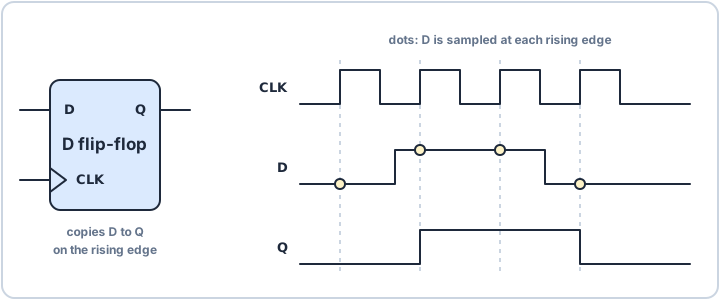
A latch changes whenever its inputs do, which makes timing hard to control. A flip-flop looks at its data input D only at the clock edge, usually the rising one, copies it to Q, and ignores D until the next edge. Between edges Q holds still, however much D wiggles. One flip-flop stores one bit.
- Rising edge: the moment the clock goes from 0 to 1, when D is sampled.
- Setup and hold: D must be steady for a short time before and after the edge. The datasheet gives the times.
- Q: the stored bit, stable between edges.
Why this matters in firmware
Every register in your microcontroller is a row of flip-flops, and the clock decides when they update. If a signal from outside, such as a button, changes close to a clock edge, it can violate setup or hold and the flip-flop may take an unpredictable time to settle to 0 or 1, a problem called metastability. The usual fix is a synchroniser: pass the signal through two flip-flops in a row. Chips do this on their input pins, and it is one reason a pin has a small delay before software sees the change.
Flip-flops are the step from circuits that only calculate to circuits that hold state and move through steps, which is what a program counter, a timer and a state machine all are.