Digital Systems
 3 min read
Logic gates
A logic gate is a tiny circuit that turns one or two input bits into one output bit. A handful of gates (AND, OR, NOT, XOR, and their inverted forms NAND and NOR) are the building blocks of every digital circuit, and the C bit operators are named after them.
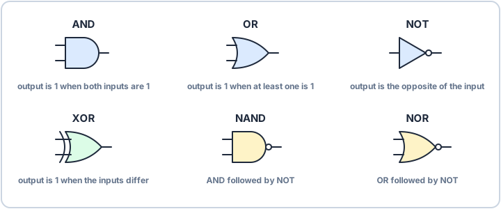
Six gates to know
Each gate has a symbol and a rule. A small circle on an output means the result is inverted: NAND is AND followed by NOT, and NOR is OR followed by NOT.
| Gate | Output is 1 when | In C |
|---|---|---|
| AND | both inputs are 1 | a & b |
| OR | at least one input is 1 | a | b |
| NOT | the input is 0 | ~a |
| XOR | the inputs differ | a ^ b |
| NAND | not both inputs are 1 | ~(a & b) |
| NOR | both inputs are 0 | ~(a | b) |
The same gates in your registers
When you write to a register, you are using gates, one per bit, in parallel. AND with a mask keeps some bits and clears the rest, OR sets bits, and XOR toggles them:
reg |=  (1u << 3);    // OR: set bit 3
reg &= ~(1u << 3);    // AND with NOT: clear bit 3
reg ^=  (1u << 3);    // XOR: toggle bit 3
XOR is also an equality check: it outputs 1 exactly when its two inputs differ, so a ^ b is zero only if all bits match.
NAND builds everything
NAND is a universal gate: any other gate can be made from NANDs alone. Tie both inputs together and it becomes NOT, since 1 NAND 1 = 0 and 0 NAND 0 = 1. Follow a NAND with a NOT and you have AND. In CMOS chips NAND and NOR are also the simplest cells to build, which is why real designs lean on them.
Gates are not instant. Each one adds a small propagation delay, and the datasheet of the chip gives the real figure. Long chains of gates are what limit how fast a circuit can run.