Digital Systems
 3 min read
Multiplexers and decoders
Combinational circuits have no memory: the output depends only on the inputs right now. A multiplexer picks one of several inputs using select bits, and a decoder does the reverse trick, turning a binary number into one active line out of many.
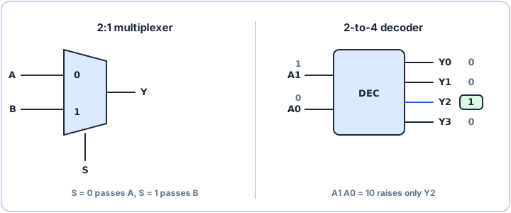
Multiplexer: choose one input
A multiplexer (mux) has several data inputs, some select inputs and one output. The select bits are a binary number that says which input to pass through. A 2:1 mux has one select line S: when S is 0 the output is A, when S is 1 it is B. As an equation, Y = S'·A + S·B, an AND-OR circuit you can build from the gates you already know.
With n select bits a mux chooses between 2^n inputs: two select lines give a 4:1 mux. Many ADCs use one internally: a mux in front of a single converter lets one ADC read several pins, one channel at a time.
Decoder: one line out of many
A decoder goes the other way. A 2-to-4 decoder takes a 2-bit number and drives exactly one of four output lines high: input 10 (2) activates output 2 and leaves the rest low. Each output is an AND of the inputs, some inverted: output 2 is A1·A0'.
| Input A1 A0 | Output driven high |
|---|---|
| 00 | Y0 |
| 01 | Y1 |
| 10 | Y2 |
| 11 | Y3 |
Where you meet them
Address decoding is the classic use. A microcontroller or processor puts an address on the bus, and a decoder uses the top address bits to raise a chip-select line, so only one device, such as a flash, a RAM or a peripheral, answers at once. The same idea appears in an LED matrix or a keypad scan, where a decoder turns a short binary number into one active row. Inside the chip, the bus matrix and peripheral selection rely on the same principle.
Neither circuit stores anything. Change the inputs and the output follows, after the gate delays.